BEARING LUBRICATION INTRODUCTION
Speed, Load & Viscosity Relationships

Bearing types, size, RPM, loading and operation environment are influencing the efficiency of bearing lubrication. Speed and load are the two key factors affecting the selection of lubricant type. When the bearing operation speed is high, the heat generation due to friction will be high. Then, in order to provide better heat transfer ability, lubricant with lower viscosity should be applied. Also, if the bearing loading is high, more viscous lubricant should be used.
Lubricant Grease & Oil
| Use Conditions Guidelines (refer to your equipment manual) | |
|---|---|
| Use grease, when: | Use oil, when: |
|
|
ROLLING BEARINGS
These bearings are characterised by they types of roller, size, number of rows of elements and the groove type. They can be designed to support both radial and axial thrust loads. A ball bearing has a point contact while the roller bearing has a line contact which affect the method of lubrications.
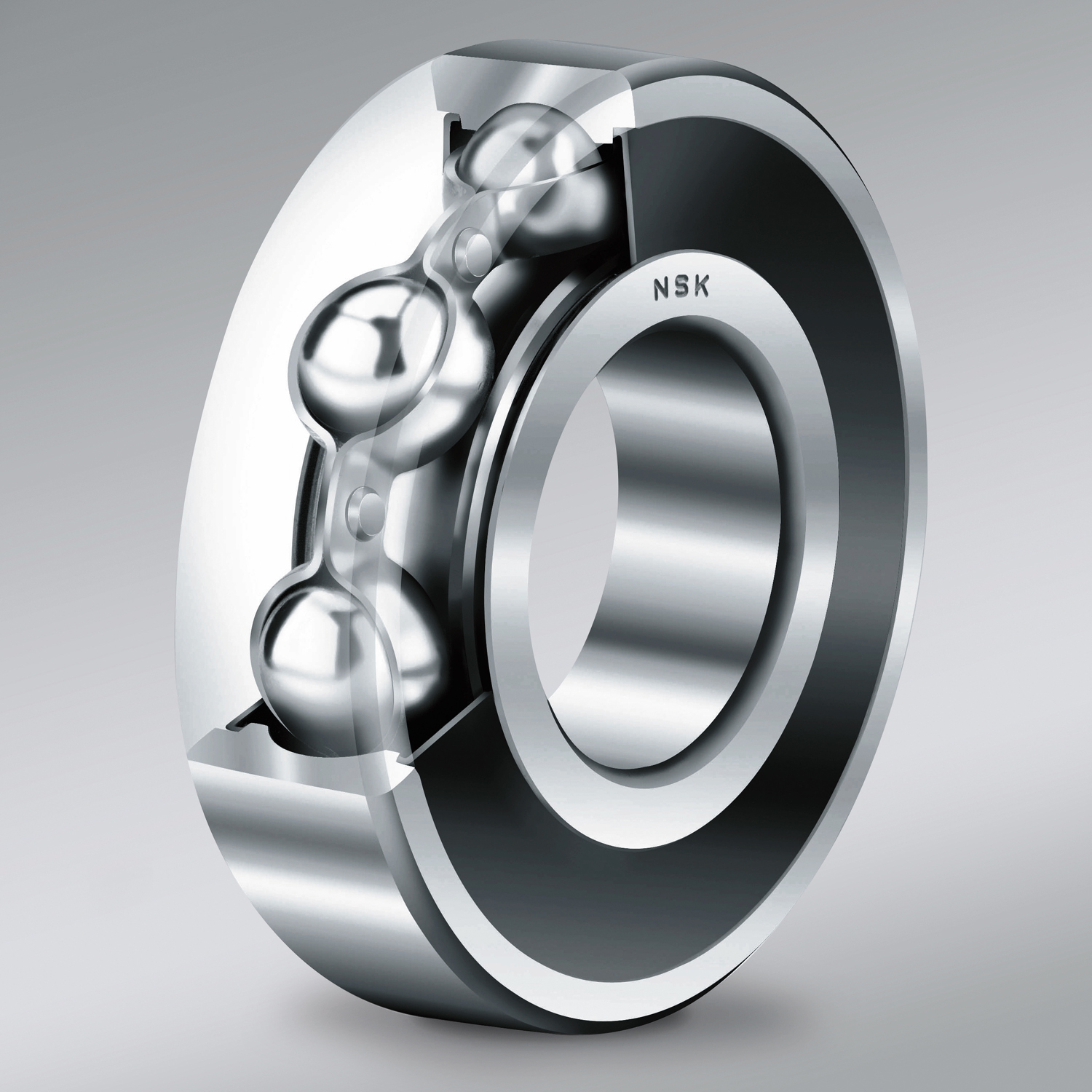
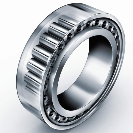
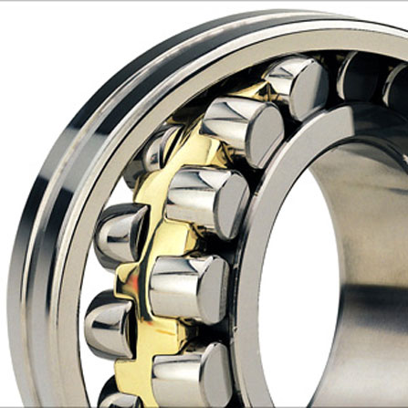
Fig 1. Ball Bearing
Fig 2. Cylindrical Bearing
Fig 3. Spherical Bearing
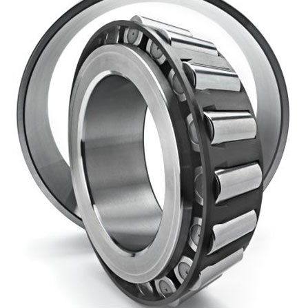
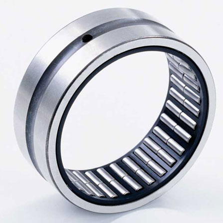
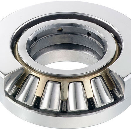
Fig 4. Tapered Bearing
Fig 5. Needle Bearing
Fig 6. Thrust Roller Bearing
Fluid (Oil) Lubrication
Viscosity, base oil type and additive type are the three main criteria in lubricant selection. `ND_m` is the speed of rolling element bearings where it equals to rpm x (ID + OD) /2. Low speed bearings have `ND_m` vales below 50,000 while values between 100,000 and 300,000 are the average speeds. Values above 400,000 are high speed bearings. `ND_m` values above 700,000 (or up to 1,500,000 use mist lubrication) is the upper limit of oil lubrication. The minimum viscosity of 13cSt is the rule of thumb for many moderate speed bearings.
To find the "Minimum Required Lubricant Viscosity at Operating Temperature", please click here.
We can also consider the minimum viscosity at the operating temperature based on the speed and the type of bearing:
| Minimum Oil Viscosity (cSt) at Operating Temperature | |||
|---|---|---|---|
| `ND_m` | Ball Bearing | Cylindrical, Tapered & Needle Bearing | Spherical Bearing |
| 50,000 | 22-45 | 50 | 65-100 |
| 100,000 | 15-20 | ~28 | 30-45 |
| 200,000 | 10-20 | ~18 | 20-30 |
| 400,000 | 7-8 | ||
| 500,000 | 6 | ||
Plot the graph of viscosity-temperature after the minimum viscosity is selected. This ensures the selected ISO grade lubricant has a viscosity greater than the minimum at the operating temperature. Generally, the actual viscosity used at the operating temperature is between 1.5-2 times the minimum viscosity. The Kappa Ratio (K) is indicates the actual viscosity of the oil being used to the minimum viscosity required. Kappa ratio equals to 4 can maximize the bearing life where the ratio equals to 1 refers to the minimum condition to prevent boundary lubrication (metal-to-metal wears). However, if Kappa ratio is too high, it will lead to bearing failure due to fluid friction and excessive heat generation.
Grease Lubrication
Base oil, additives and thickeners are the basic elements of greases. Greases are usually limited to rolling bearings with speeds up to `ND_m` values of 350,000 for ball bearing, and 150,000 for spherical bearings. The thickener type of the grease is based on the type of application, water resistance and operation temperature. When switching to other grease type, it is recommended to flush all the oil grease out of the bearing in order to prevent incompatibility of new and oil greases. If two incompatible grease are mixed together, softening may happen causing the grease to leak out of the bearing and damage the bearing.
The grease grade is classified by NLGI which is determined by the application method and bearing speed. NLGI No.1 grease have good low temperature dispensing ability while NLGI No.3 is suitable for higher speed or electric motor bearing to reduce churning and heat creation. NLGI No.2, 1, 0 or 00 grades are suitable for centralized grease system, and NLGI No.00 or 000 are being recommended for gearboxes which require semi-fluid greases.
The grease base oil viscosity is an important factor. 150-220 cSt@40℃ is suitable for shock loading applications. 75 to 120 cSt@40℃ greases are suitable for bearing speed between 200,000-300,000 `ND_m` without subject to shock loadings. Grease base oil with viscosities 25 to 75cSt@40℃ can be used for pumping operation at low temperature, or for high speed bearing (300,000 to 400,000 `ND_m`). Grease base oil with viscosities higher than 460 cSt@40℃ are good for high temperature, high loading conditions with water resistance ability. If the operation subjects to high centrifugal forces such as coupling, base oil viscosity of 800 cSt@40℃ or even higher should be applied.
Extreme Pressure (EP) additives such as Molybdenum (Moly) in greases is a solid additive. It is not recommended to use "Moly" greases in moderate or high speed rolling bearings because those solid additives can accumulate inside the bearing components. Also, if the operating speed of the bearing is over 1,600 rpm, "Moly" greases should be avoided because Moly can be centrifuged out of the lubricant and causes bearing failure. No matter the bearing speed is high or low, "Moly" greases can damage the surface of the bearing metals and greatly reduces the bearing life, and induces high replacement cost and downtime cost for the users.
Many lubricant manafacturers use Liquid extreme pressure additives to provide protections against shock loading and metal wears. However, the oxidiation stability can be reduced when these additives applied. This is not favour to life-long sealed bearings. Meanwhile, sulphur based extreme pressure additives can corrode yellow metals like copper, bass or bronze.
In order to solve and avoid the problem mentioned above associated with solid additives and extreme pressure additives, Steel Shield ABF Technology was invented. It is now replacing the old lubrication technologies. Click here for more.
Quantity And Interval Of Relubrication
The quantity and grease type for relubrication must be follow strictly to the manufacturer manual. The following information provides a general rule-of-thumb.
Re-Greasing Quantity:
`G=xDB`
where:
`G` = Grease quantity (grams)
`D = OD` (outer diameter) of bearing (mm)
`B` = Width of bearing (mm)
`x` = 0.005 (source NLGI)
`x` = 0.004: approx. annual regreasing (from FAG Bearings)
`x` = 0.003: approx. monthly regreasing (from FAG Bearings)
`x` = 0.002: approx. weekly regreasing (from FAG Bearings)
Re-Greasing Interval:
Common method recommended by SKF and FAG is showned:
`t=K((14,000,000)/(nd^(1/2))-4d)`
where:
`t` = Relubrication interval (hour)
`K` = Bearing factor (`K`=1 for spherical roller, tapered roller and ball bearings with thrust loads; `K`=5 for cylindrical and needle roller bearings; `K`=10 for radial ball bearings)
`n` = Speed (RPM)
`d` = Bearing bore diameter (ID) or shaft diameter (mm)
The SKF Chart
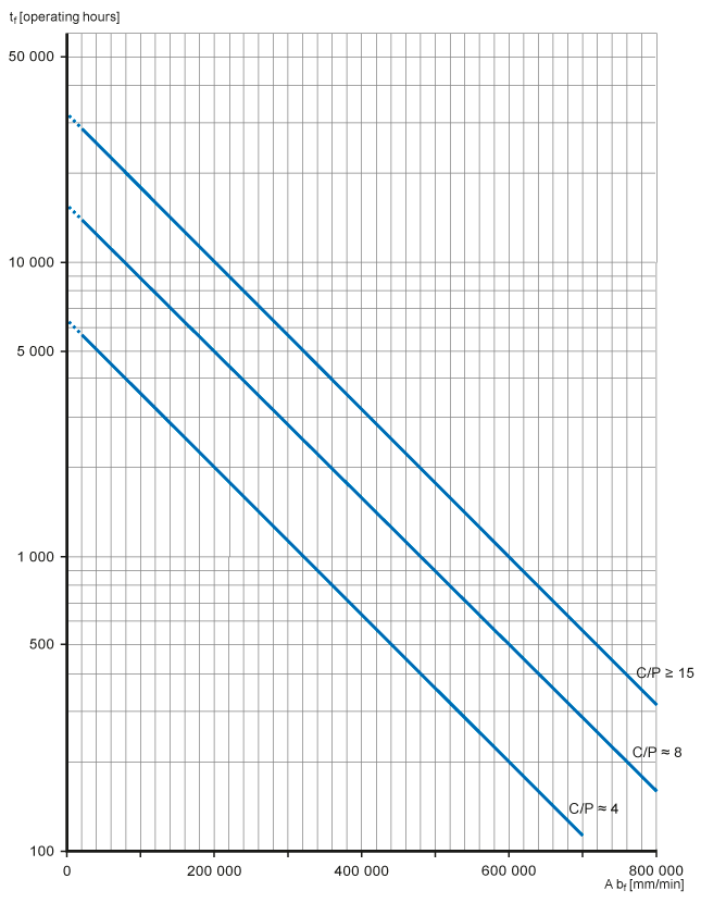
Diagram 1 - Relubrication intervals at operating temperatures of 70℃ (160℉)
Ref.: SKF. Relubrication intervals (Accessed: 25th Feb, 2016).| Bearing Type | Bearing Factor, K |
|---|---|
Radial ball bearings
|
1.0 |
| Cylindrical roller bearings - non locating | 1.5 |
| Cylindrical roller bearings - locating | 2.0 |
| Cylindrical roller bearings - locating with a constantly acting small axial load | 4.0 |
| Cylindrical roller thrust bearings | 10 |
| Spherical roller bearings | 2.0 |
| Spherical roller bearings - axial or combined load | 6 |
| CARB bearings | 2.0 |
| Tapered roller bearings | 2.0 |
| Thrust ball bearings | 2.0 |
| Spherical roller thrust bearings - axial load and rotating shaft washer | 4.0 |
Where:
C/P is the load ratio (C/P ≥ 15: Light to normal load; C/P ≈ 8: Normal load; C/P ≈ 4: Heavy load)
n = Rotational speed (RPM)
dm = Bearing mean diameter (mm) (=0.5(d+D), valid for horizontal shaft and clean conditions. For vertical shaft, halve the interval. If the ring rotates, use DN valves instead of ndm)
The FAG Chart
FAG Bearings developed different charts to identify the relubrication interval.
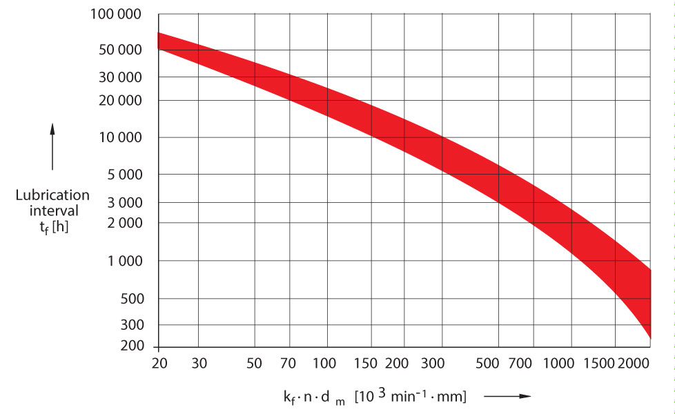
Diagram 2 - Relubrication intervals from FAG
(Ref.: FAG Bearings Ltd. Rolling Bearing Lubrication. FAG publication No. WL81115/4EC page.36)The methods above indicate the ideal conditions, and therefore, they yield very long relubrication intervals. FAG Bearings uses factors to reduce the hours between re-greasing which depends on the harshness of the operating environment.
| Bearing Factors | |
|---|---|
| Bearing Type | Bearing Factor, K |
Deep groove ball bearings
|
|
Angular contact ball bearings
|
|
Spindle bearings
|
|
| Four-point bearing | 1.6 |
| Self-aligning ball bearings | 1.3-1.6 |
| Thrust ball bearings | 5-6 |
| Angular contact thrust ball bearing (double row) | 1.4 |
Cylindrical roller bearing
|
|
| Cylindrical roller thrust bearings | 90 |
| Needle roller bearings | 3.5 |
| Tapered roller bearing | 4 |
| Barrel roller bearing | 10 |
| Spherical roller bearing (w/o lips) | 7-9 |
| Spherical roller bearing (w/ centre lip) | 9-12 |
*: For bearings which are loaded radially and contantly axially
For varying axial loads, K=2
The factors above are significant in the estimation of re-grease intervals. Also, good judgement is necessary to obtain a realistic data.
| Adjustment Factors | |
|---|---|
| Conditions | Multiply hours by: |
Effect of dust and moisture on bearing contact surface
|
|
Effect of shock loads & vibration
|
|
Effect of (dynamic) loads
|
|
Effect of bearing temperature
|
|
Some engineers stated that grease must be applied twic as often for every 10 or 15℃ increase above 70℃:
|
|
Effect of air current passing through the bearing:
|
|
•For the present of centrifugal effects or vertical shafts (depending upon sealing): multiply by 0.5-0.7
•Actual/Rated of 0.1 = 10% load